[gview file=”http://b1gtuna.com/wp-content/uploads/2015/08/AudioSplitter1.pdf”]
우선 대부분의 에러들은 수정했다. 그리고 많은걸 배웠다. High-pass / low-pass의 계념도 다시 정립했으며 OP-AMP의 기본적인 모드들 (-ve feedback / +ve feedback)도 이제는 잘 이해가 되는듯하다.
키보드 이야기
[gview file=”http://b1gtuna.com/wp-content/uploads/2015/08/AudioSplitter1.pdf”]
우선 대부분의 에러들은 수정했다. 그리고 많은걸 배웠다. High-pass / low-pass의 계념도 다시 정립했으며 OP-AMP의 기본적인 모드들 (-ve feedback / +ve feedback)도 이제는 잘 이해가 되는듯하다.
정리하다 보니 뭔지 모르는 파츠들이 나왔다.
MCU들:
Op-Amp들:
FET:
쩝 Op-Amp 스팩 읽는 법부터 배우고 와야겠다.
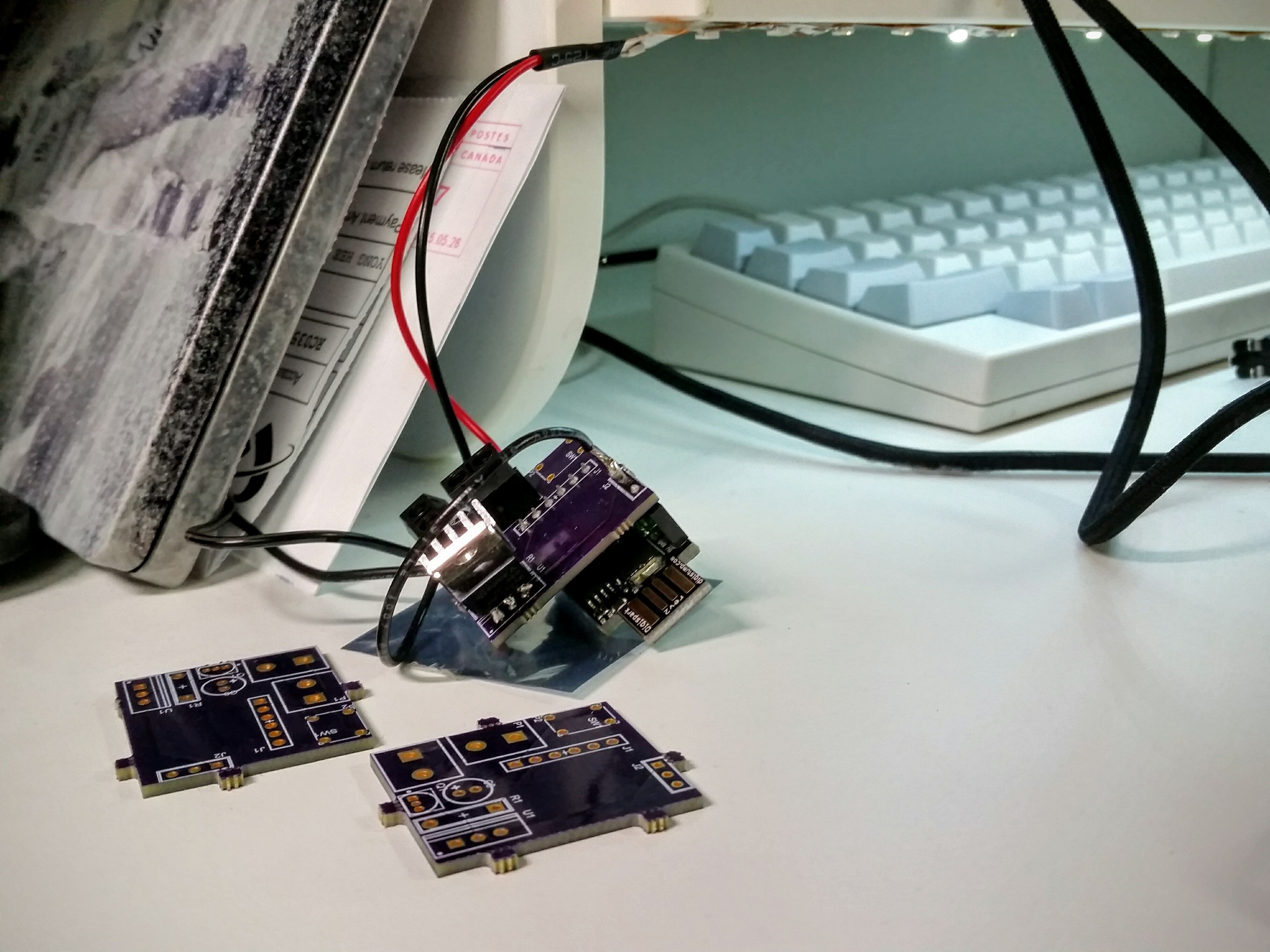
1. No GND loop to the MCU
2. 2k7 ohm R at the gate of 2n3904 is too big. LED not as bright. 2n3904 has 200mA capacity for collector-emitter. I’d like to saturated it. Assuming a current gain of 15, 13mA is all I need at the base. (3v3 – 0.65v) / 13mA is 203ohm.
3. Without a proper push button, electrical noise generates false input, resulting in random LED toggle
4. Should have labelled the PCB better. Hard to figure out which pin is what
5. Need to extend support for multiple LED